
In the first of an occasional series the good people at Ron Daley’s talk us through basic PX maintenance. This month Michael Daley tackles common indicator problems.
There’s no doubt that the P range was a huge success for Piaggio. Factor in the licence produced machines and there are, quite literally, hundreds of thousands of them still on roads around the world.
Although it’s still possible to find low mileage machines that have been loved and cherished, there are also plenty of rough examples out there. Unsurprisingly it’s usually the latter that seem to end up in our workshops!
Enjoy more Scootering Magazine reading every month.
Click here to subscribe & save.
When trying to resolve any wiring issues it’s important to take things back to basics at the first opportunity. Unfortunately, even when any excess insulation tape’s been stripped away, the loom doesn’t always make sense. This isn’t helped by some poor-quality wiring diagrams. We recently created our own, much clearer, diagrams and they can be accessed via our website.
Charging and ignition
Most people don’t realise that all wires on the Vespa PX are in some way linked. Due to the nature of the AC power source, in certain circumstances a broken wire can take everything out on the scooter.
Top Tip: Check all wires for any breaks carefully. One thing that throws most people off when reassembling the wiring is the colour change in the wiring diagrams.
Top Tip: Not all wires connect colour to colour. For example, when the ignition is connected to the main harness, white joins to a red and white wire.
Top Tip: Make sure all earths are connected! There are several earth wires that need connecting. Without the earth this may result in the scooter not starting.
What type of system?
Top Tip: When ordering electrical components it’s important to know whether you have an AC or DC model as not all components are interchangeable.
• AC is a constant power which comes from the stator.
• DC is regulated power and comes from the battery.
• The DC (Direct Current) power source is that drawn from the battery to power up certain parts of the electrical system.
• The two main components that draw power from the DC power outlet are the horn (which has two yellow wires) and the starter motor (long black wire connected to the engine side).
Top Tip: Your battery must supply at least 1.5 to 2 amps to power the electric start. If your battery is defective or has drained below that figure the kick-starter must be used.
The battery gets its power from the stator, but this first passes through the voltage regulator. The regulator’s job is to limit the power supplied to both AC and DC outlets and prevent damaging electrical components.
What goes where?
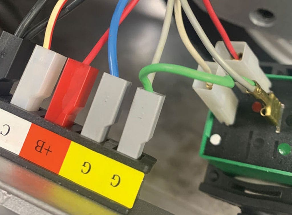
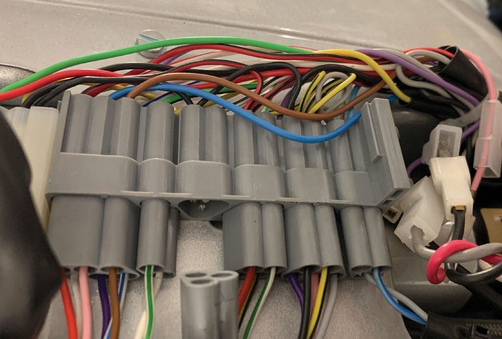
The main harness connector block is located behind the horncast. It looks complicated but is very user friendly, as each connector has a unique shape so it’s impossible to connect the wrong component.
Top Tip: If a poor connection is suspected, check that the bullet connections are correctly located in the terminal block. They are held in place with a ‘barb’ which can twist out of shape and allow the wire to move out of place.
Indicator circuit
Top Tip: Before trying to find any wiring problems, always check that the bulb is working. Even the best mechanics sometimes forget to check the obvious!
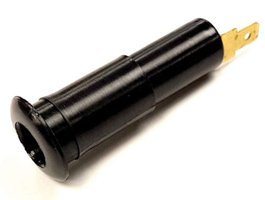
The indicators have a separate relay which is supplied by a green wire coming from the regulator. To conserve power the PX’s indicators flash alternately front and rear. It’s the relay’s job to control this function by switching power between the two wires.
Each indicator has an external earth, either fitted on the inside of the indicator unit (rear) or externally between the frame and the indicator (front). The earth wire MUST be fitted correctly!
Top Tip: Corrosion can sometimes occur on the back of the indicator switch’s circuit, which will affect operation. This usually requires a replacement switch.
Rear indicators aren’t working?
Most of the time this is caused by a bad earth or poor connection on the side panel.
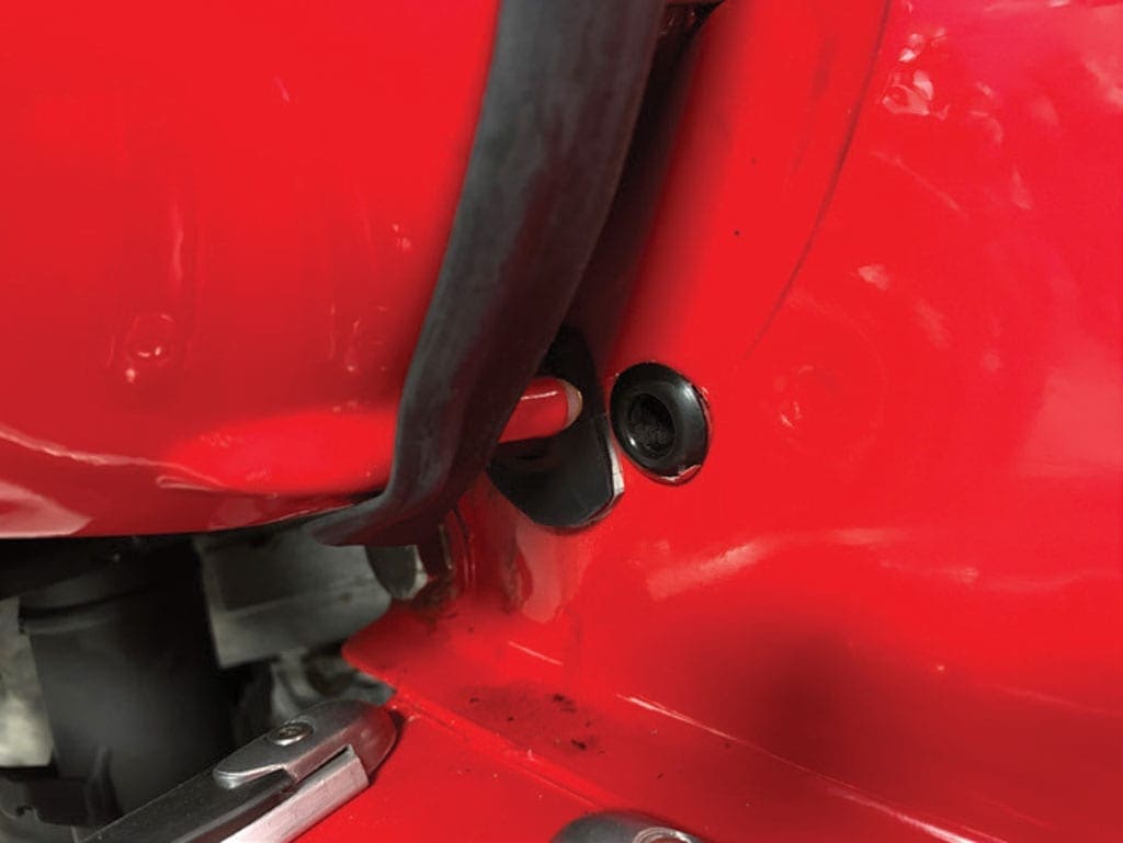
Side panel pin: although they’re part of the panel’s fastening system the side panel pin and its hole are critical parts of the indicator system. The pin and/or the hole can sometimes corrode and may need gently rubbing down to ensure a good connection.
Side panel hook: the side panel hook is not only used to hold the side panel in place, but it also makes one of the best earths on the panel. If you’re struggling to make the indicators work, check the hook and the hook bracket (which is mounted inside the frame).
Not only should the hook pull the panel tightly into place, it’s also worth checking that there isn’t corrosion or paint preventing the hook from making a connection and allowing it to have a good earth.
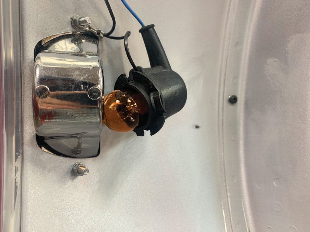
Front indicators aren’t working?
Front indicators are generally the least problematic electrical item on a PX. The most common fault on the front indicators is a damaged switch or a ‘dry’ soldered connection which allows the wire to become detached.
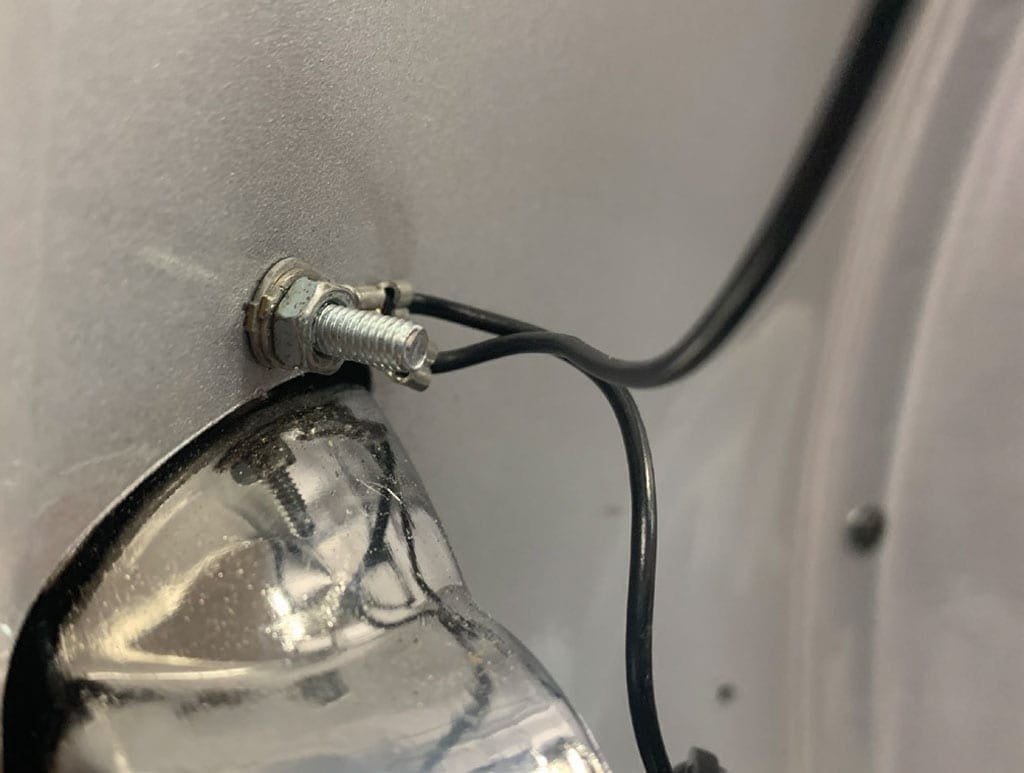
Always make sure that the earth and power wire are connected to the indicator socket and then check the earth wire is tight against the frame. If the nut has worked loose this can cause a ‘bad earth’.
Top Tip: Be careful when tightening the indicator lens screw, it’s quite easy to crack the lens.
Indicator warning light
Contrary to popular belief, the indicator warning light is only powered by the rear indicator, Piaggio’s logic being that a rider can see the front is working, but not the rear. When the warning light doesn’t work, it’s usually because of a problem at one of the rear indicators.