In the last edition we looked at the Lambretta brake system in general. This month we will look at cable issues with both the front and back brake. As long as there is a cable fitted the brake should work, however quite often because of improper routing or maintenance the brake is not as efficient as it should be.
Front brake
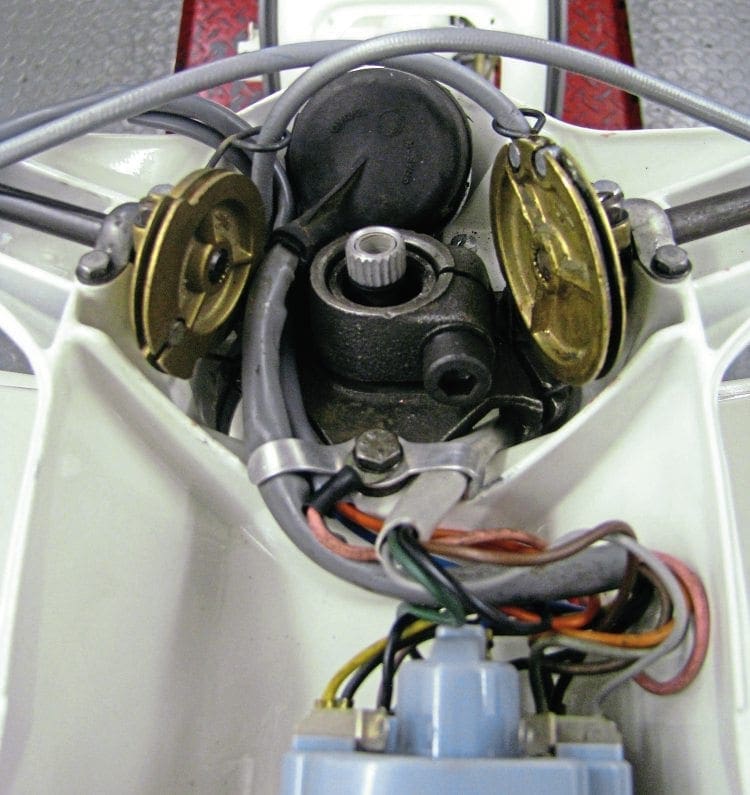
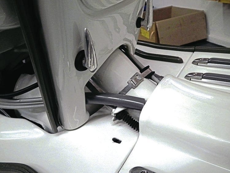
To get the most tension and pressure on the cam or calliper it’s best to try and get the curve on the cable as smooth as possible. This is not an easy job because to do so it will need to cross from the left to the right and then back again to attain the best possible route. Start with the outer cable only from the inner recess in the light switch housing and loop over to the left hand side guide in the headset where it will follow down the fork stem.
This will give the smoothest curve possible. As it goes down the left hand side of the stem it then crosses back over to the right underneath the horn and on the fork tube. Make sure it fits through the wire retainer at the top of the tube then follows down through the fork bolt clip and then curves round in to its recess on the drum or disc.
Enjoy more Scootering Magazine reading every month.
Click here to subscribe & save.
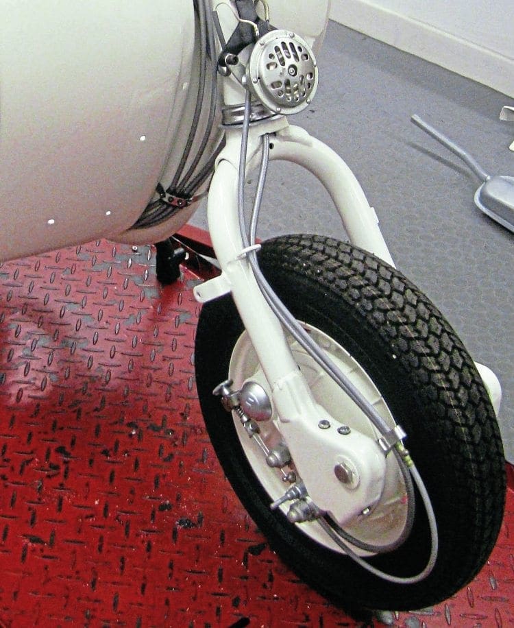
One of the problems can be the outer cable itself. Not all cables are manufactured to exact lengths so the loop from the fork bolt clip may be too long. If so the outer will need cutting down to get the desired length. If the cable is too short then it is no good as the loop will be too acute and there is the possibility of too much friction stopping the inner from returning back when it has been used.
The best method is to follow the curve of the speedometer cable and front tyre. Try not to get the loop to go past the edge of the front tyre and by doing so you will get the most natural curve. If you need to shorten the length to get the desired curve use a good set of cutters to get a clean cut. When you have made sure you refit the steel stop on the end of the outer surface. Now you have the desired length you can get on with fitting the inner.
Firstly check there is no wear on the lever or pin itself. A small amount of slack in the area will be greatly exaggerated — if so replace it. Fit the inner cable in to the lever recess and apply a coating of grease along its entire length. Now feed in to the outer all the way until it comes out the opposite end. Before fitting the brake adjuster make sure the outer cable is sitting fully home in the light switch housing. If it isn’t as soon the lever is pulled in the outer will pop in the recess but leave too much slack on the cable.
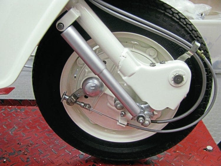
Now it is time to fit the adjuster. Before doing so make sure it fits perfectly in to the brake arm and if not file the edges until it does. Now turn out the thumbwheel adjuster so 2mm of thread is exposed on the thumbwheel. This will allow you to wind it in slightly and take up any slack without having lost any adjustment. With the adjuster in place fully depress the brake arm at the same time pulling the inner cable towards it. With an instant marker make a mark where the inner cable reaches to the 5mm pinch bolt on the adjuster.
Where that point is, bend a 1800 loop in the inner cable. Take the adjuster out of the brake arm recess and wind the thumbwheel out as far as you can. Now place the inner cable through the 5mm pinch bolt and clamp where it was marked and tighten it up. Depress the brake arm and fit the adjuster back in position, there should be enough length to do so.
Now wind the thumbwheel in where it was originally and you should have a perfectly tensioned cable. One that is not too slack or too tight which would allow the shoes to bind. This can be fine-tuned by turning the thumbwheel one or two turns either way but otherwise it should work the brake perfectly.
The reverse pull system
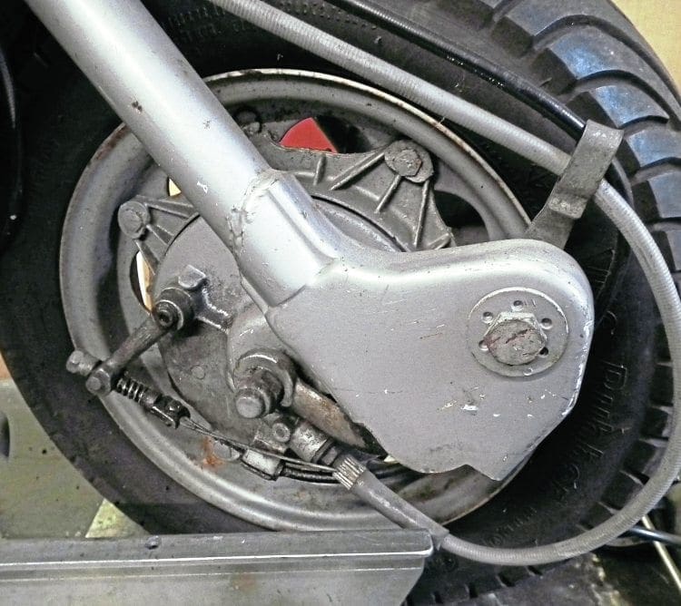
The reverse pull front brake system was first devised by technicians at Lambretta Concessionaires in the late 1960s. The idea came about to improve the performance of the disc brake even though it can be used the same way on a drum hub. It works by making the cable around half a metre shorter thus allowing more pressure to be applied to the caliper as there is less flexing of the inner cable. The conversion is a worthwhile one and is fairly simple to do.
Firstly you need to drill out the cable recess in the hub itself. This needs to be done with a 6mm drill bit making the hole as straight as possible. As the hub is aluminium it won’t need too much pressure on the drill to go through. Once this is done remove the thumbwheel from the adjuster and from the calliper side push the adjuster through the cable recess, making sure the spring is on the upper side as this will act as the tensioner. A good tip is to place a 6mm washer between the spring and the recess so the spring won’t push off centre under pressure. Where the adjuster comes through the recess place another 6mm flat washer followed by a 6mm nylock nut. This must be a nylock nut for safety reasons to prevent it from coming undone.

Instead of the cable coming down the forks and round the front wheel it is now reversed and enters from the top of the forks. Where the cable enters in to the caliper an adjuster is fitted to control the cable length. Originally this was done using an LD adjuster block but these are hard to find. A good replacement is a Vespa clutch cable adjuster which will do the job perfectly.
Finally you will need to make a clip to hold the cable in place and stop it fouling on the front tyre. This is mounted on the top damper bracket and requires a slightly longer 6mm bolt so both the damper and clip can be fastened securely. Over the years there have been many clips made available to buy, from rather elaborate steels ones to pieces of welding wire that are chromed. A good way to make one is by using a metal coat hanger looped round for extra strength. One thing to remember is not to make it to long otherwise it can foul on the front mudguard when it is turned, especially if it is an SX type.
Again the same procedure is followed when measuring the inner length of the cable as already described, except it is from the other way round. The cable adjuster is now what controls the final length just as the thumbwheel adjuster did. Feed the cable through the clamp and tighten it up, you will then have a perfect working reverse pull brake. What you will notice is as the brake lever is pulled in the tension is greater as the cable is much shorter. You should now find you have much improved stopping power.
Rear brake cable
Fitting of the rear brake cable is one of those jobs on a Lambretta we all try to avoid. Not only is it difficult to fit but also as it’s by the engine it will be dirty and require you getting underneath the frame to feed it through correctly. There are several steps that can be taken to make the job easier and are well worth doing to do the job properly.
Make sure everything is clear and out of the way and remove the bridge piece entirely. Not doing so will make it much harder and almost impossible when trying to feed the cable through. Make sure all the linkages on the brake pedal are good and replace if worn. If the cable clip that fits underneath the adjuster block is rusty then replace it. These have a tendency to snap off and if they do then the cable can rub on the rear tyre. Finally if the clamp bolt for the cable on the linkage is worn or rusty just replace it as it can be difficult to feed the cable through or tighten up otherwise.
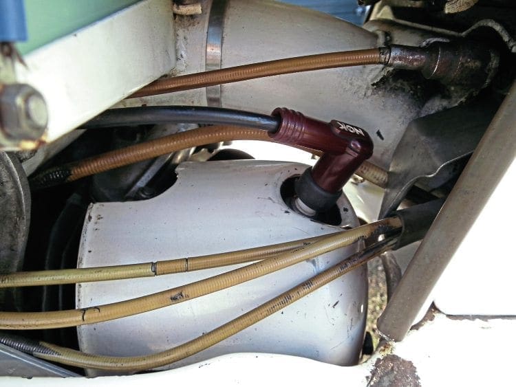
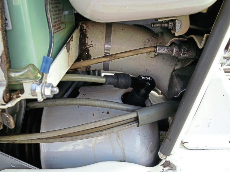
The first procedure is to fit the outer cable correctly. Feed one end under the engine mount tube through the cable clip on the adjuster block. Follow it underneath the left hand side of the gear pulley and tie bar in to its housing on the engine casing. Make sure the cable fully sits in to the top hat and apply a small amount of grease to both to prevent them from seizing in the future. The other end must now go over the head cowling to the left hand side of the cable deflector by the choke and in to the top hat and housing on the frame. Note where it goes in the housing that it sits underneath the two gear and clutch cables. It should now be in perfect position. If it is you will notice that it sits flush along the engine casing before arcing over the head cowl in a slight curve. This curve is important because it allows the cable to flex when the engine moves, for example over a bump in the road, this is even greater exaggerated when riding two up. If there is no curve it is possible for the brake to be applied under the said circumstances causing it to overheat and bind on the hub as it gets hotter.
If you are happy with the length and curve you can now fit the inner cable starting off at the thumbwheel adjuster end. When doing so make a 180° bend on the inner cable like it was explained for the front brake cable to go through both side of the clamp. Take caution here though so the exposed end doesn’t protrude more than 5mm past the clamp. If it is too long then it is possible for the much thicker cable to hit the back of the casing, causing it to stop the brake arm moving far enough, so the brake itself won’t work. Once the adjuster is fitted, grease the cable and feed through the outer. Feed right through so it is just exposed past the top hat at the other end. Originally it would have had a rubber gaiter but they can be a pain to fit right.
It is up to you if you wish to leave it off or not but if you do leave it off make sure that you apply plenty of grease to the exposed inner. The final part is to thread the inner through the pinch bolt and this is where you must feed it correctly to allow you to tighten it up correctly.
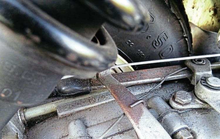
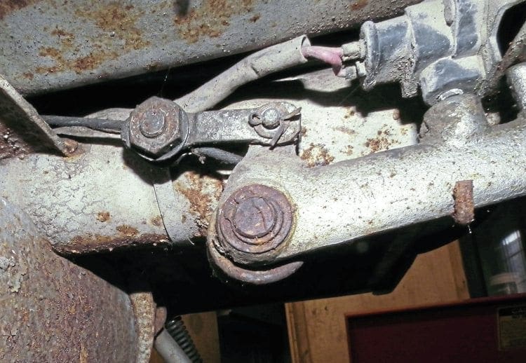
Push the cable through and it should appear just above the stand strut. From here it has to thread through the hole on the pinch bolt. As you can’t see the angle of the hole and you are now in an awkward position under the frame, make a mark on the end of the bolt to show which way the angle of the hole is. Turn the bolt so the angle is now the same as the cable and feed it through. Once through the cable must feed underneath the linkage but above the brake pedal pivot. That way the cable moves freely when the pedal is depressed. Feed it all the way through until the adjuster is sitting flush in the brake arm. Before tightening turn the thumbwheel out slightly as described earlier, allowing you to fine tune the adjustment afterwards. Using a set of strong mole grips clamp the end of the cable underneath the brake pedal, this won’t fray the end as it is soldered.
Now pull hard and fully tighen the 19mm nut on the pinch bolt. Release the mole grips and check the movement of the brake pedal. While you only want minimal movement you must have some to allow flexing of the cable as previously mentioned. The cable will stretch slightly but you can now adjust to the correct tension using the thumb wheel. You should now have a fully working back brake.
As with any cable operated system, the better the fitment of the cable the more efficiently it will work. Regularly check and grease the cables and if changing it is best to change both the inner and outer. Obviously if you have snapped a cable out on the road then you will just change the inner but if it is a winter overhaul for instance then change both. Look after your brake cables and they will look after you, making you come to a halt safely.
Words & photographs: Stu Owen