Long journey home, getting dark, lights starting to flicker? It’s no joke if your lights pack up — time to look at the wiring (the lighting circuit)…
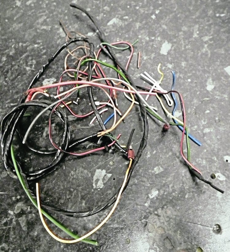
Lambretta wiring (the lighting circuit) can be one of the most frustrating parts of regular maintenance. Many owners find wiring a ‘no-go zone’ and see the wiring circuit as a mass of tangled cables they dare not touch. This doesn’t have to be the case, and if tackled in a certain way can be very easy to understand.
Compared to most modern motorcycles and scooters which run indicators, warning lights, senders and so on Lambretta wiring is very simplified and basic. It only has to run a front headlamp with high and low beam, side light, speedo light, brake light and horn. Because of this there are only a small number of wires going through the loom making each circuit easy to follow.
Enjoy more Scootering Magazine reading every month.
Click here to subscribe & save.
Tracing the source
Electricity: we can feel it but can’t see it. The best way when trying to understand wiring is to find the source and follow it round to its final destination. In this case the source is the stator, so when trying to fault find always start there first.
For this article we will use the standard electronic stator and normal AC wiring loom as our example as the majority of road going Lambrettas use this system. The first thing to check is if power is coming out of the stator. There are four wires coming out of the stator with red, white and green running the ignition circuit. The other wire which is yellow in colour (on some SIL stator plate’s brown) is the power wire for the lighting circuit and the only one we are interested in. With the engine running, place a 12v bulb on one side of the wire and the other to earth on the engine. If the bulb lights up then you know that electrical current is being created in the stator.
From there it can be traced either to the junction box or (in the case of a non-junction box loom) to the regulator. If it does go in to the junction box then a yellow wire follows it out of the junction box to the regulator anyway. The current is fed out by a brown wire which goes directly in to the main loom on the frame. This brown wire now travels straight up to the headset. Again do a similar test with a light bulb and if it lights up you know you have power to the headset.
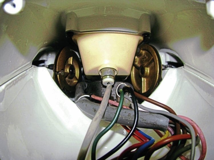
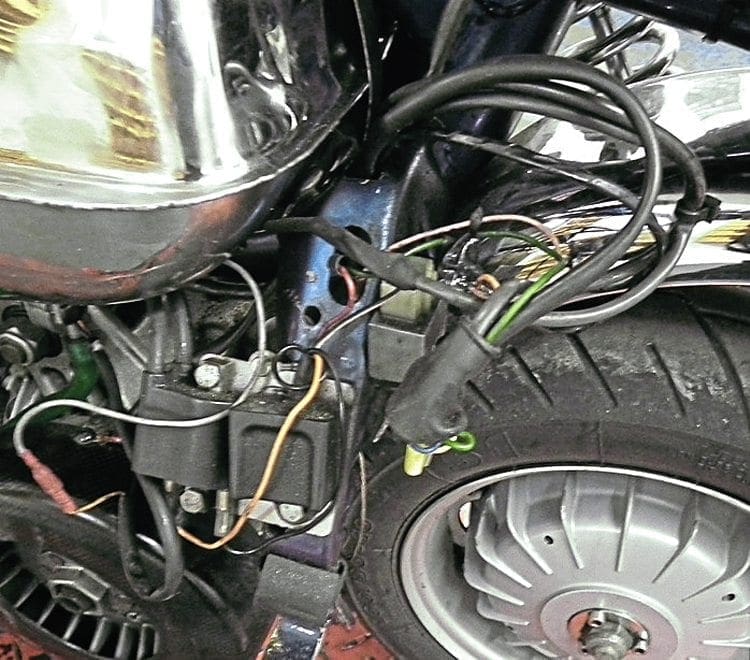
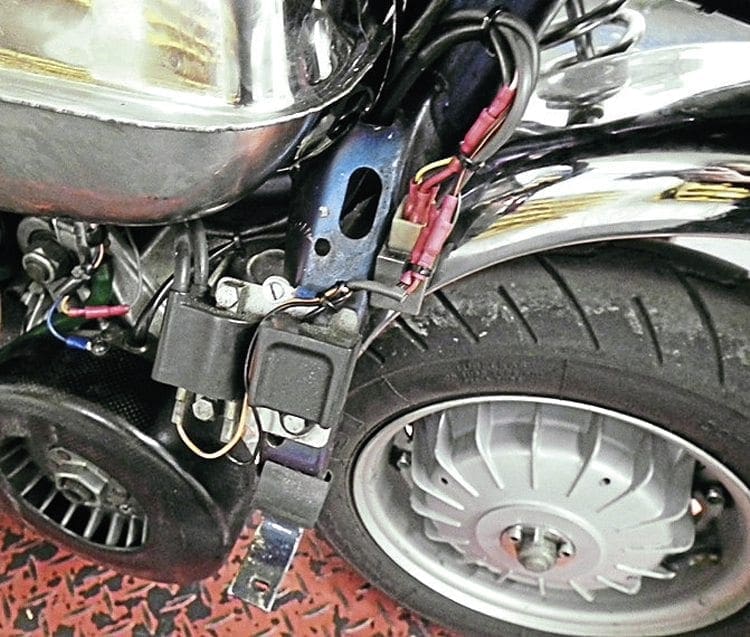
The headset junction
Now it is established that electrical power has made it up to the headset, if there are any problems with the lighting circuit we know it must be within the junction box area. The headset junction box is what gives most Lambretta owners problems when understanding the lighting circuit. It is the most congested area in terms of wiring as it is the point where electrical power arrives and leaves.
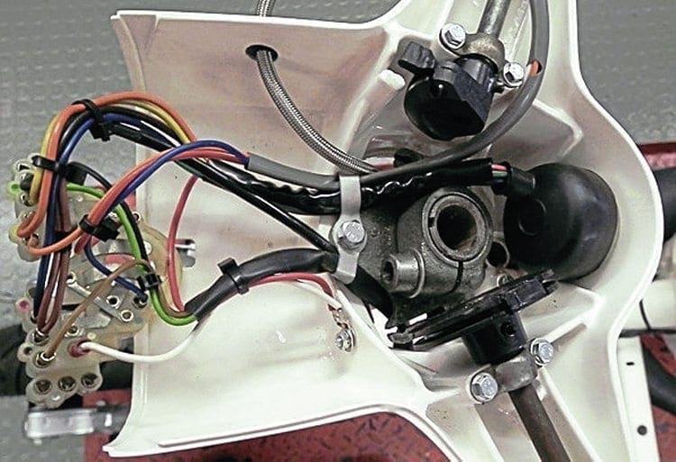
Again, if it is broken down in to its separate elements then it is easier to understand. Firstly the green wires, whether from the loom or the ignition key, can be ignored as they are not involved in the lighting circuit. The rest of them are colour coded brown to brown, black to black, orange to orange etc. Any that are single wires do have their own plug in the junction box, for example the yellow or white.
Main lights
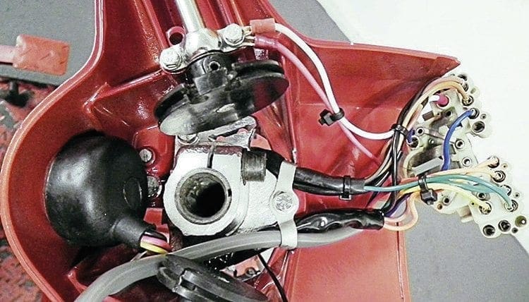
One wire that does confuse people is the side light. Originally it was grey off the ignition switch but on most modern switches is blue; consequently some modern looms don’t have a side light wire. If that is the case then the blue or grey wire from the ignition switch sits in a junction on its own. If there is no wire from the loom you can spur off the brown wire to supply power to run the sidelight.
To check the high and low beam take the blue and red wire from the dip switch and do the light bulb test to check they have power. If all is okay when plugged in, both should work, If either of them doesn’t then check the bulb is fully connecting on to its contacts on its base.
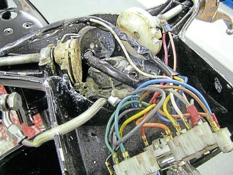
The other important thing is to check the earth wire from the junction box is working correctly. Innocenti originally connected the earth wire from the junction box to headlamp rim but this does have its drawbacks. Firstly because the headlamp has to be in place to check the lights it shakes about violently with the engine running with the headset top removed. Secondly the connection to the rim can get corroded and is one of the main reasons for the head lights not working properly.

An easy solution is to run the earth wire from the junction box directly to the headset. This can be either to one the front bolt that holds the gear pulley rod in place or tap in to the aluminium of the headset and bolt it directly there. Slightly off subject the pink earth wire for the ignition switch can be connected in a similar way. That way if the ignition-switch needs removing it can be done with ease rather than the having it connected to the headstock bolt as was done in the factory.
If there is still a problem with lights not working the only place it can be is the ignition switch itself. Some aftermarket ones can be poor to say the least and can often be the cause of a circuit not working. The solution here is to fit another ignition switch. This will only take a couple of minutes to plug in and doesn’t have to be fitted in to the headset. If everything is working with the new switch then you know the other is faulty and needs replacing.
Horn
The horn has two wires, one which connects from the loom and the other, which is white in colour, from the high/low switch. Again you can do the bulb test to make sure power is flowing but remember you must press the horn button to make the circuit complete. If all is okay any problems can now be traced to a faulty horn.
Here are a couple of quick tips which can help when wiring the horn during a rebuild. Firstly extend the two wires which plug in to the horn. Allow a slack of 7cm on each wire and fasten to the loom in a bow shape. If you then need to remove the horn at a later date the extra length of the wires makes them more accessible where they plug in to the horn. Only the horn grill needs removing, not the complete horn casting itself. Secondly put a male and female connecter in to the white wire at the top of the headset before it travels down the horncasting. That way, if you ever have to change or remove the high/ low switch the horncasting doesn’t have to be removed as the white wire is unplugged in the headset.
Rear light and brake light
This is the final destination of the lighting circuit as it now leaves the headset. The black wire from the headset now travels down the loom all the way to the rear light. Again do the bulb test from the black wire to earth.
Once you know power is there, any problems can either be traced to faulty light connections (often corrosion on the contacts) or a bad earth. It is always best to connect the earth wire from the light unit to one of its fixing bolts on the frame. Always use a ring connector and always remove a tiny amount of paint round the hole to make sure of a clean contact.
In the case of the brake light, if the rear light bulb is working then that should be too. If it is not the problem lies within the brake switch itself. Two reasons for a faulty brake light switch are either corrosion due to water entering or a crack in the switch due to fatigue from the pedal constantly pushing it.
SUMMARISING
While trying to explain wiring in its simplest of forms it can be sometimes difficult to visualise what is being described. Here are a few points to help you along.
1) Follow the current from its source and check each part of the way round the circuit to make sure the current is present.
2) Plug each wire in to its correct colour coded socket. In the case of extending or replacing a wire make sure it is still the same colour.
3) Always make sure earth connections are secure and free from corrosion
4) If current is not flowing from a component fit another one to check if the original is faulty.
5) If a bulb is not lighting up don’t forget to check the bulb itself hasn’t blown.
6) If fitting a new switch or loom cut the wires to the length they are needed, more so in the headset to avoid a mass of unwanted wires.
7) Finally, be patient and take your time when problem solving. Remember it’s a process of elimination as you go round the circuit.
Words & Photography: Stu Owen
This article was taken from the August 2016 edition of Scootering, back issues available here: www.classicmagazines.co.uk/issue/SCO/year/2016