From the early 1960s, the Vespa used both an ingenious and a simple method of operating the choke mechanism on the Dellorto carburettor with only detailed changes in its design up to the demise of the two-stroke Vespa scooter. Dave Dry helps us get that choke system set up properly…
(Body copy) Like the other controls on the Vespa, the choke is cable operated, but with the substitution of a thin wire instead of braided (twisted filament type) cable for the moving inner element. Apart from this component, the cable appears on the outside to be a traditional Bowden cable set up using the flexible plastic-covered outer sheathing of the original design.
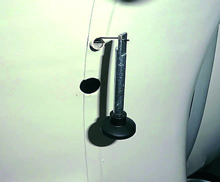
The other design differences to be noted are in the terminal ends of the solid inner cable. In operation, one end of this wire has to connect to the choke knob that slides within a tube that is welded into the front of the monocoque chassis (located under the seat nose and adjacent to the fuel tap lever). This tube is a clever part of this relatively simple design, as it features a machined cut out slot in a section of the tube close to the chassis proper. Additionally, close to the opposite open end of the tube,is a rolled-in ‘collar’ that is radially machined so as to serve as a stop for the end of the outer cable on final assembly. More about the purposes of the cut-out later.
At one end of the choke, the inner cable/wire is either a small ‘pip’ soldered in place or a looped and twisted ‘eye’ (for later model types). The type of end design utilised depends on the kind of carburettor choke activating mechanism fitted to the carb itself, but both serve the same purpose – to hook onto the carb choke opening mechanism lever.
The means of connecting to the choke actuating knob is, in principle, very ingenious and utilises the end of the wire/cable being purposely bent into a miniature ‘Z‘ shape. This, on final assembly, is inserted into a drilling through the shaft of the choke knob and, when correctly positioned, enables the cable to sit flush with the flat milled at the end of the knob’s shaft.
With the principle of the cable terminations now outlined, the actual locating of the cable into the chassis can be explained:
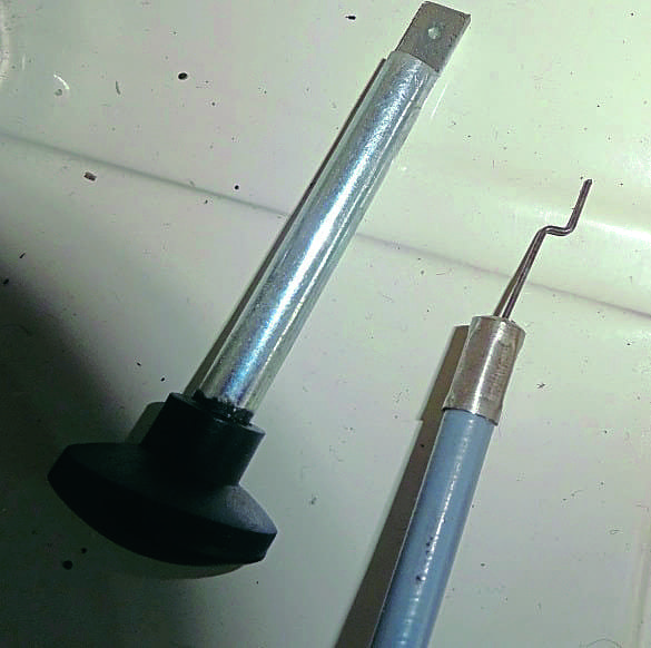
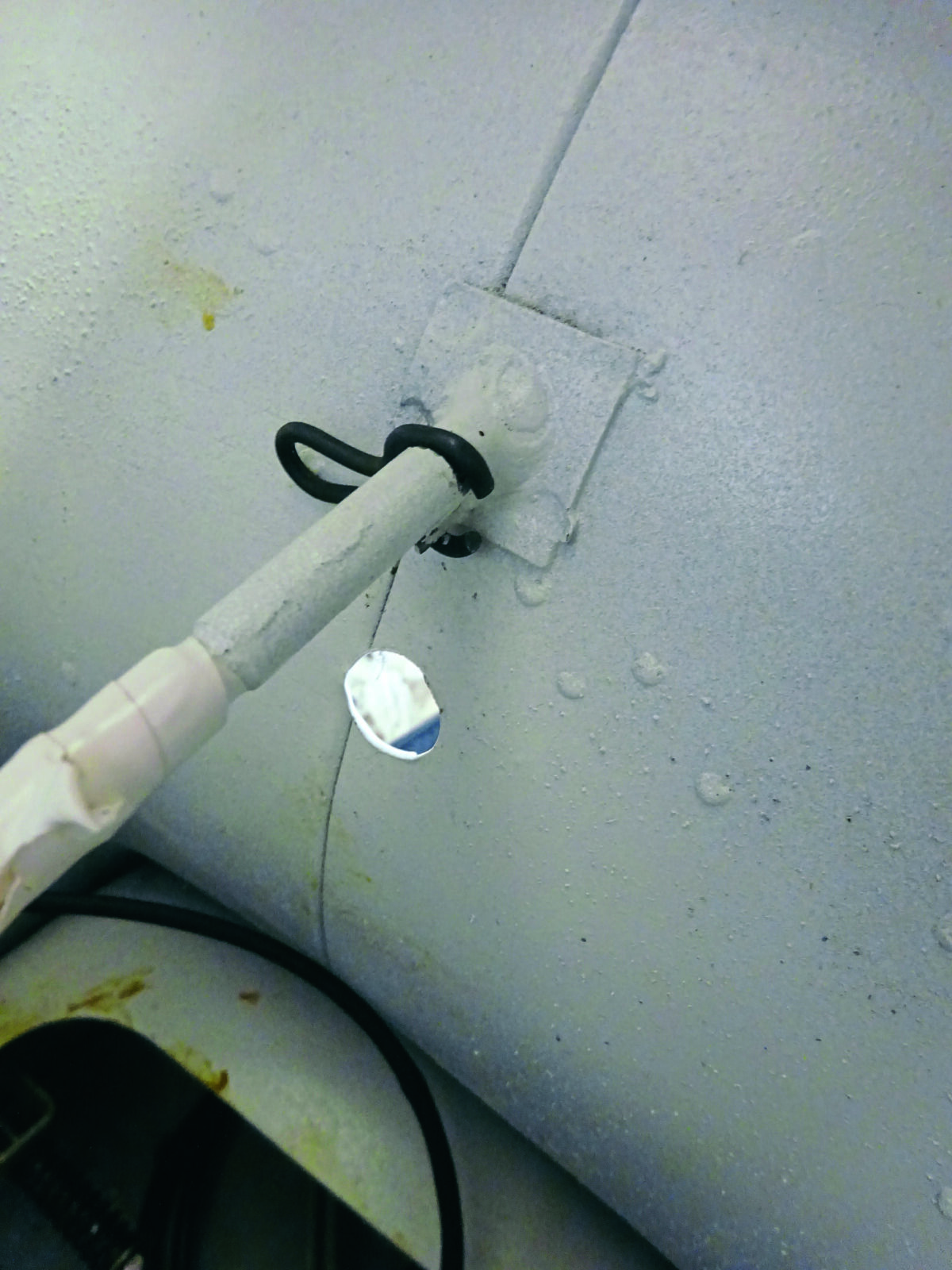
1: The Vespa choke system is simple in its design and reliable in its operation when set up properly.2: This is a close-up of the cable and choke knob, so that we know what we are dealing with.3: Feed the ‘Z’ sectioned end of the inner cable through the tube from the inside of the chassis, so it appears at the outside end of the tube. The operating knob can now be positioned, and the choke cable/wire and shaft of the choke knob can be drawn into the monocoque via that tube. A little lubrication in the form of a light grease, possibly Vaseline, is often utilised to both prevent any rusting in the future and to smooth the operation of the choke.4: The outer cable can now be fed over the inner cable/wire to the point where it can be located into the chassis choke tube so its end can butt against the milled ‘end stop’ section. At this point it must be pointed out that, some remade choke cable outers are, sadly, manufactured with a plated brass end cap that is too large in diameter to fit into the chassis tube, so this cap and the adjacent plastic coating must be removed for the above instructions to be viable. The next stage in the installation is to feed the carb end of the complete choke cable through from the monocoque towards the engine and carb. This should follow the path of the throttle cable.5: Now remove the choke mechanism from the carb and locate the outer choke cable into the end stop of this part. The inner cable/wire will now extend towards the sprung-loaded choke lever mechanism and can be hooked into place before the mechanism is once again refitted onto the carb.
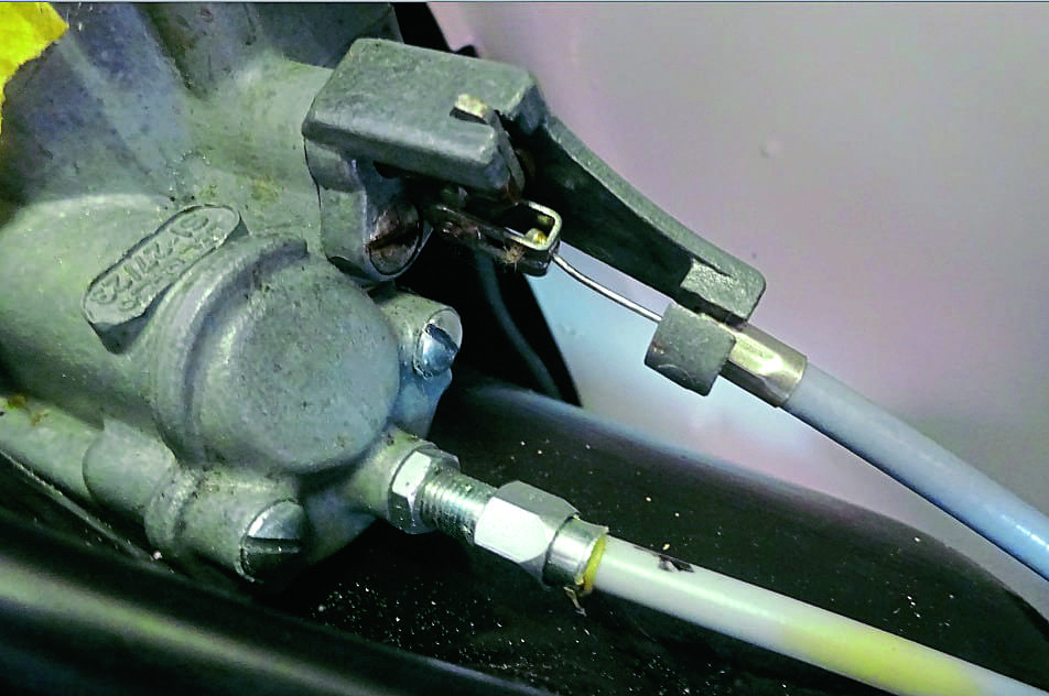
If the choke knob is now operated, it will return due to the pressure from the spring-loaded carb choke mechanism.6: To complete the assembly, you should have a small, ‘G’ shaped wire clip, which, in a perfect world, would have been slid over the chassis choke tube before the above cabling operation. If you locate this wire clip over the cutout in the tube previously mentioned and twist it through approximately 90 degrees, it will then bear against the choke knob shaft via this cutout – locking itself in place in the process due to the springiness designed into this part – hopefully forever. Due to the spring friction applied by this clip, the choke knob will now stay in place when in the open position, despite any pressure from the carb mechanism, thus opening the choke within the carb and allowing the engine starting sequence to be undertaken. On successful starting of the engine, the choke knob can then be pushed back to the closed position. The only other slight snag, if you have the ‘pip’ type inner, is that the end ferrule on remade choke cables might not allow the inner to pass through the ferrule. If this is the case, the ferrule must be opened out with a suitably sized drill bit.7: This is how everything should look at the carb end. Check to see that everything operates correctly, and that the choke plunger lifts and returns as required. Job done
Words & photos: Dave Dry
Many thanks for the help and advice of Matthew Phillips of Vespa Parts Finder
Mark started life on two wheels aged 8 on a Mobylette in his Grandfather’s back garden. It was in the blood; Mark’s Great Uncles raced sidecars at the TT, once finishing 5th. His Grandfather was a speedway rider. As for Mark, he once held a licence to race motorcycles in Italy, has completed the ‘Iron Biker’ challenge around the Alps and one day wants to ride around the entire coastline of the UK on a motorcycle..