Darrell Taylor continues his look at the two-stroke top-end, this month delving into squish band width and MSV, and starts to put some of the pieces of the power puzzle together…
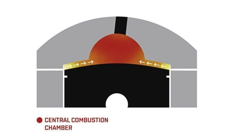
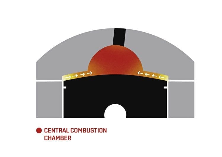
A commonly used phrase in head design is ‘squish clearance’ but ‘squish velocity’ is a term that will be new to some, it is a measurement that refers to the speed with which the fuel/air charge is compressed/squished out of the squish clearance gap between piston and head, and plays an important role in making a modern two-stroke engine more efficient. The speed term in common use is referred to as m/s or ms (metres per second) and is calculated as a maximum squish value, so the term MSV is often used. The maximum value is as a result of the changes which occur in use, mainly to operating rpm. So an example MSV calculated at 22ms at 9000rpm, increases to 29ms at 12,000rpm, so the max rpm alters the max value. A whole load of variables within an engines design will make major differences to the final number, so the specific engine’s bore, stroke, con rod, exhaust duration, peak operating rpm, combustion chamber shape, squish clearance, squish band width, squish band angle and compression ratio are the major players. But other end-user variables like fuel type, oil ratio etc. need to be considered, albeit to a lesser extent.
Enjoy more Scootering reading in the monthly magazine.
Click here to subscribe & save.
So what MSV are we looking for?
When all the values are calculated the aim is to produce a design which sits between 20 to 30 MSV. That is the defined range which the industry has formulated over the years, coming from engine manufacturers and two-stroke design software providers. The main point for me is that the big players in the two-stroke engine market like Yamaha, KTM, Rotax, Polaris etc. have the largest research and development budgets in the world, and the race engine manufacturers have a need to produce results which deliver performance in one form or another. So the saying we don’t need to reinvent the wheel’ is quite relevant. We can trust a lot more in the information which can be extracted from these players, as long as it’s relative to the engine which it is being compared to.
So it wouldn’t be good to copy a liquid-cooled YZ250 head onto a 200cc clubman equipped tourer, but quite often a comparable motor can be found with a similar bore and stroke, cooling and rpm range, with a requirement for good torque and reliability. So something like the stock Yamaha Blaster 200cc air-cooled quad would be interesting to look at. One of the last models at the end of a long production period, with a cylinder layout which most Yamaha engines had, the style of which the TS1200 was based around, would for example be a good design to learn from.
Is width important?
The squish band angles were covered last month, but the width also makes one of the biggest differences to the velocity… so how wide or narrow should the squish band be? The trend coming from major manufacturers is to use a narrower band width for higher rpm designs, as often seen in road/race or gearbox karts, often as low as 15% of the overall head area. Higher torque requirement engines like MX trials for road use, or even race use with lesser gears, tend to use wider 45% to 55% of head area. The most popular/ commonly used in the two-stroke heyday and still in current times is around the 50% figure, that being 50% of the total head area that is formed from squish band on a central type combustion chamber. This has quite a bit of maths in order to calculate, as it’s not the case that 50% of a 54mm bore is a 27mm band width (13.5mm each side) it’s nearer to 16mm (8mm each side when calculated).
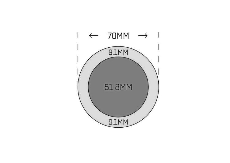
So in order to save mathematical headaches for those wanting simple answers, I have another yardstick which is a bit easier to calculate: If for example you have a 70mm cylinder head width, and require a more average approximation of the desired squish band width of say 45%, then take 70 and deduct the magic figure of 26% (51.8) = 18.2mm (that’s 9.1mm each side).
On a 66mm bore that would be 8.58mm
On a 54mm bore be 7.02mm
On a 40mm bore be 5.2mm
By comparison
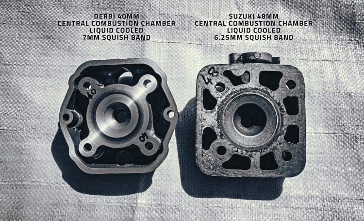
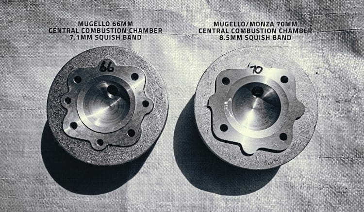
I decided to head to the garage and drag a few cylinder heads out to compare and found a Mugello 225 head with 70mm bore to be 8.5mm, a Mugello 200 with 66mm bore to be 7.1mm, so not too far off what I work to myself if I were looking at width alone. I also found some liquid-cooled cylinder heads. Liquid-cooling tends to push the MSV up higher, one example from Derbi at 40mm was 7mm, Suzuki at 48mm was 6.25mm, Polini 52mm race kit 8mm. These examples are all about 1.5mm bigger than my yardstick, so when calculated out are pushing nearer the known and accepted 50-60% head area figures which liquid-cooled motors tend to push towards.
Putting the pieces together
At this point a few pieces of the ‘jigsaw of cylinder head design and compression’ can start to be pieced together: The yardsticks previously provided in article two (April edition) of 2% stroke for squish clearance, along with parallel squish on a central combustion chamber, and the 45% of bore squish band width calculation when put through some design software calcs produced the following results:
On a 70mm bore with 58 stroke the 2% squish value is 1.16mm, the approx 45% figure is calculated out by deducting 26% (51.8mm) leaving a band width of 18.2 total (9.1 each side) typical trapped compression ratio of 6:1 and a con rod length of 107mm, with a max operating rpm of 8000 running on a parallel-squish, central type combustion chamber. The variable now is the exhaust ports duration, so I ran some calcs to see how results changed:
At 160° exhaust — 25.03ms
At 170° exhaust — 24.57ms
At 180° exhaust — 24.02ms
At 190° exhaust — 23.37ms
These all work out really nice, and just sit mid-point between 20 and 30ms which is desirable, and could give a man with a lathe a yardstick to work to, without having to invest in expensive design software.
Design software is available and makes the calcs easy to work with and allows input changes to be made, in order to get the design working better, as it’s often the case that the head you’re working with has limitations to what can be done to it. Sometimes the band width cannot be made wider and you have to work with what you’ve got, and change the values in other areas to get the design to work, this speeds up the process considerably. I use Tom Turner’s TSR software on the heads which I do, that version of the software being 10 years old now, but still a great tool. There are lots more out there: Bimotion, Mota, Port 2T, and Torqsoft to name but a few which can all be found online.
What you might have worked out from all this is that with the huge number of variables that exist it’s like having an old fashioned combination lock on a bicycle, but with 100 rings to turn that provide endless input options. It’s important to point out that despite the combinations of designs which are out there, they all work to a certain extent, and the industry’s theory in itself is slightly flawed in one major way… which is that the squish clearance does not remain static. A squish of 1.2mm on the bench, will at max rpm reduce to approx 0.6mm so a 22.71ms figure in reality at max rpm will be 38.47ms. Don’t let that put you off though, as the designs are industry tested standards, and proven over many years.
Still, the biggest concern when designing the head is whether the compression is too high. Although performance will be stronger… damage can result if it’s too high. So I’ll cover measuring the volume and compression ratio in a coming edition.
Darrell Taylor
This article was taken from the June 2016 edition of Scootering, back issues available here: www.classicmagazines.co.uk/issue/SCO/year/2016

Enjoy more Scootering reading in the monthly magazine. Click here to subscribe.
Scooter Trader