How far can we reasonably take a SIL 200 engine, with each step giving the most ‘Bang for Buck’ (more power per pound spent)? Darrell Taylor finds out…
The story so far
Last month’s instalment brought an end to the ‘bolt on section’ of the report, resulting in a 15.33bhp/15.41tq output using the original SIL cylinder with re-jetted carb/free-flowing filter, head gasket removed and an expansion type exhaust fitted. This now begs the questions: how does the cylinder perform so well, what part of its spec is producing this result, and how did the spec come about? So before moving on to changing the porting or head specs let’s see what we have to start with.
Enjoy more Scootering reading in the monthly magazine.
Click here to subscribe & save.
Let’s get measuring
With the engine removed the first measure was an accurate check of the squish and head volume to calc out the compression ratio with the head gasket removed as per its last run. The repeated squish checks averaged out at an outer dimension of 1.05mm, 1.16mm is a standard yardstick on a 58 stroke so this was a fraction tighter but still acceptable on a new crank/ bearing engine set up. I say this as when an engine gets more miles and wear the big-end/small-end bearing clearances will change, and will show a bigger squish clearance while compressing solder. But in a running engine it results in a smaller clearance — this is a handy way to check for engine wear, especially useful on race engines running tighter clearances. The head was then removed and bore greased to seal the top ring and reassembled to measure the volume using a burette and petrol/oil mix, the total volume was 27cc to the top of the plug thread. The plug thread volume was 2.3cc, thus leaving 24.7cc as the combustion chamber/squish volume this equates to a top dead centre/ uncorrected compression ratio of a fraction over 9.04:1 (6.02:1 corrected) which is healthy enough to make decent power with it at its current port spec. I wanted to also retrospectively check what we would have had had before removing the head gasket, so refitted the standard gasket in place. I could then not accurately measure the squish as it barely touched on a doubled up twisted section of solder at approx 2mm+ but based on no head gasket giving 1.05mm squish, adding the 1.5 head gasket would make it 2.55mm. The volume check showed 29.7cc in the combustion chamber/squish area that this equates to 7.67:1 uncorrected (5.18:1 corrected) which is a very low compression figure.
So with such an inefficient squish we now had a better understanding of why we got such an improvement when the head gasket was removed. SIL engines are very inconsistent though, and not all will come fitted with a thick 1.5mm gasket. I have previously seen 0.7mm head gaskets used in SIL gasket sets, so was the big gasket intended to be used during that difficult running in stage and at the point of stripping down to torque the head then replaced with the 0.7mm? If so then the compression with the 0.7 would be somewhere between the two at around 8.4:1 uncorrected (5.6:1 corrected).
Next up was a cylinder check. The preferred method is to measure the ports’ heights individually on the cylinder in mm as opposed to using a degree wheel which would need to be the size of a dustbin lid to get near the accuracy required. This is also something that you may have witnessed when putting ignition timing marks on with a dial gauge as opposed to a degree wheel, finding quite a difference between the two. This measuring situation is made even worse when trying to take a port measurement from a low-sitting transfer port, with no light shining through, and an uneven chamfer on the port edge… it almost becomes guesswork! The next problem comes when marking out the ports for cutting which is often done back in mm on the bore so mixing the two different measuring methods from degree wheel to mm I find isn’t accurate enough.

Before removing the cylinder to measure and calculate the port durations it’s important to have a piston height measurement, where it sits in the bore in relation to the cylinder/head gasket surface that the ports are measured from/to. Some heads have rebates, some have a spigot which sits into the bore and then there’s a whole range of gasket sizes, so a port which measures 37.3mm down from the top of cylinder (in this case for the exhaust port) is only that if the piston’s outer edge is sitting perfectly flush with the cylinder top its working distance is to the piston’s top dead centre. This is also subject to change from engine case to case with the base gasket face machining being different, hence why kit manufacturers sometimes supply a selection of gaskets.
Knowing that we had removed the head gasket, the head had no rebate (or spigot) and the squish-clearance outer edge was flush with the cylinders top, then it follows that the measured squish clearance is equal to the piston height. This means the piston is 1.05mm below the cylinder, thus making the 37.3mm exhaust measurement a working measurement of 36.25mm. The rest of the original ports with piston height calcs deducted are as noted below. I like calling it piston height as it makes for a logical process, because if a piston is 1mm below (-1mm) you deduct 1mm from the measurement, if its 1mm above (+1mm) you add it on. Be careful of this fact if using online or two-stroke porting software to calculate as it’s not quite as clear.
The calculations
The below port heights were then calculated on a PC program to provide the duration in degrees of opening:
TEST CYLINDER STANDARD PORT HEIGHTS (58/107mm CRANK)
Exhaust port top edge 37.3mm -1.05mm = 36.25mm = 167°
Transfer ports top edge 46.75mm -1.05mm = 45.70mm = 124°
Inlet port bottom edge 95mm -1.05mm = 93.95mm = 141°
Piston skirt length (inlet side) 71.1mm
Blowdown
If we deduct the transfer degrees from the exhaust degrees, 167° -124° = 43° then divide by two and we get 21.5°. This 21.5° is referred to as a ‘blow down’ figure. This relates to how many degrees the exhaust port is open for in order to do its work of expelling the exhaust gas from the previous ignition/combustion event, before the transfer ports open.
This is a very important figure as if the exhaust gas is not sufficiently expelled out of the exhaust duct prior to transfers opening, then it will proceed to use the next available port to try to exit. Of course the next available are the transfer ports which are supposed to be delivering the next batch of fresh fuel/air charge, so this conflict will cause the upcoming fresh charge to have its purity contaminated with hot exhaust gas, and cause the flow direction to be reversed, resulting in a loss of efficiency and power as well as an overall hotter running engine.
So if we look at the cylinder layout as a whole I can see that it is ‘blow down limited’ at only 21.6°. A commonly used blowdown figure for production motors in modern use, especially with limited gears available, is circa 25-27°. This leaves us 5.5° shy of that higher figure.
Transfer and inlet
At 124° the transfer figure itself isn’t too bad and for the operating rpm range that we are working around or aiming for, 5500rpm to 8000rpm roughly matches peak power on most commonly used exhausts, so it has sufficient degrees/ duration to cope. The inlet degrees, 141°, is not too bad either, as being a piston port motor it’s in danger of suffering spit back and poor low speed running at higher durations which I’ve found when above 160°, and often for little performance gain.
These higher inlet timings can run well on higher compression ratios for racing and higher operating rpm set-ups and can be cleaned up with advance retard modules to provide longer burn time to make use of the extra charge supplied, but they are not of interest on a ‘Bang for Buck’ motor. A modern motor needs to be closer to a reed motor in terms of riding flexibility, so keeping the inlet duration low is what we will do and should we wish to try longer duration a trim of the piston skirt can be done in the future then replaced if not happy with the results.
Does size matter?
The port durations are one element of the port specs but not the only consideration. The port size in terms of width, shape and their internal duct flow angles into the cylinder and the roof/floor angles all contribute to the overall performance.
So an exhaust port which is low on duration, but has lots of area from a big width, can be as effective as a high duration on a small width. The same applies from where material is removed from to make a port larger, in some areas you will most certainly lose power and in others most certainly gain power.
The measured port widths of the standard test cylinder are:
Exhaust port: 41.34mm
Transfer port: 31mm
Inlet port: 41.30mm
I was quite surprised with the transfer width figures, being considerably wider than most modern/standard cylinders and an exhaust port and inlet port width at around 62% of the bore’s 66mm width. Bearing in mind maximum width on a race use cylinder is around 70% with high quality piston rings which can sustain this width.
History 1, 2, 3…
These findings prompted a visit to the workshop while writing this, to dig out a more modern (yet still old) cylinder to provide a gauge of size. I found an old standard TS1-200cc cylinder although a reed cylinder it’s the same 66mm bore size, and found it had the following widths:
Exhaust port: 40.4mm
Transfers: 32.4mm including dividing bridge approx 1.4mm
Inlet: 40.4mm
So the test SIL cylinder I had, in terms of port widths, is bigger than the old TS1-200!
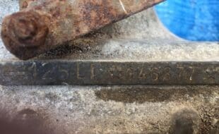
How did this come about? I decided to dig a bit deeper as the SIL 200 motor is often referred to as a ‘Stage-4’ and I rang AF Rayspeed up to see if they could shed any light on the subject. Ben and his father Ray kindly provided the story that at one point in time, due to there being no 200cc cylinders available in India, SIL was supplied with an Italian Stage 4 ported cylinder from Two Four Accessories of Croydon where Arthur Francis worked and had always offered Stage 4 tunes to customers. I went on to ask if the cylinder supplied was from a specific model as I’ve found one particular Italian cylinder to have really wide transfers as standard at a similar width to the SIL cylinder, of which they said, “Yes, it was one of the rarer wide transfer cylinders.” I went on to ask if there were any other changes of note which had been made to the original SIL engine over the years,” to be told: “Very few, most noteworthy was the larger stator wire retaining plate which eases the passing of the wires through, the change from 22.9mm crank pin to the common Japanese sized 22mm and the longer finned flywheel and cowling arrangement,” and that’s about it!
Porting work
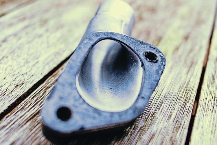
Intrigue over, back to porting plans for the cylinder which was only going to be a basic tune with no elaborate extra ports. The cylinder ports were of ‘mass produced Indian quality’ and obviously over the years the casting mold edges will have suffered somewhat, but were fairly well shaped still. The inlet port wasn’t too far off matching the inlet manifold, and same with the exhaust stub. So I did a clean-up of both those areas, not that big gains can be had there (unless a major step exists in the direction of flow) and the transfer port entries at the gasket surface received similar work. It was just a mild tidy up to the gasket dimension and the existing cut outs which allow passage into the transfers from the bore, squared up to provide more access area.
The inlet port was quite misshapen so was squared off and its lower timings edge cleaned up just a touch, to make a level line over its width while retaining a good corner radius, increasing the duration only a touch by doing so. Then its top edge was raised slightly to increase the port area, but note that that doesn’t change the duration. Do remember that the cylinder wall must still support the piston rings, so be careful not to raise it too much. The transfer ports were most misshapen and so required squaring off and levelling on floor/roof on both left and right sides of the cylinder. This resulted in just a mild change to the duration but a large increase in port area which was wider than a TS1-200 already! The left and right edge cutting is the most difficult and often missed areas, these ports operate effectively very much like putting your thumb over the end of a hosepipe to direct flow, and this is similar to how a transferred charge enters into the cylinder.
The exhaust port received the largest material removal of all, as in order to achieve the blowdown increase I was hoping for, the only option available was to raise the exhaust port duration (as opposed to widening the port). This was because, when using the standard piston and ring arrangement which won’t tolerate wide exhaust port widths (and was already wide enough) means the area needs to come from increased height.
One other option available would be to lower the whole cylinder, which reduces transfer duration at a greater rate than it does exhaust duration due to the cranks angle/rod/pin position towards the bottom of its stroke having a greater swing than towards top, so in turn increases blowdown. But as we wanted to retain (for now) the standard 58/107mm crank, then we had no adjustment on cylinder position available. So decisions on final exhaust duration had to be made, and those plans are based around the final exhaust system which was planned which happened to be a NK rally.
This exhaust featured as a best in test a few years ago on an exhaust system shootout here in Scootering. As a side note, the downside of a test like that is that all it really tells you is what exhaust system works best on the exhaust duration of the test machine, and is limited to straight swap testing without receiving jetting or ignition changes, gearing adjustments during road testing… but I digress. The exhaust duration I settled upon was 188°.
This was deduced following a series of previous tests I did on another development motor where I found the NK pipe liked that figure best. Rather aptly it was only about 3° away from the 185° of the TS1 equipped test machine which Scootering had used in the previous exhaust test where the NK came out very well.
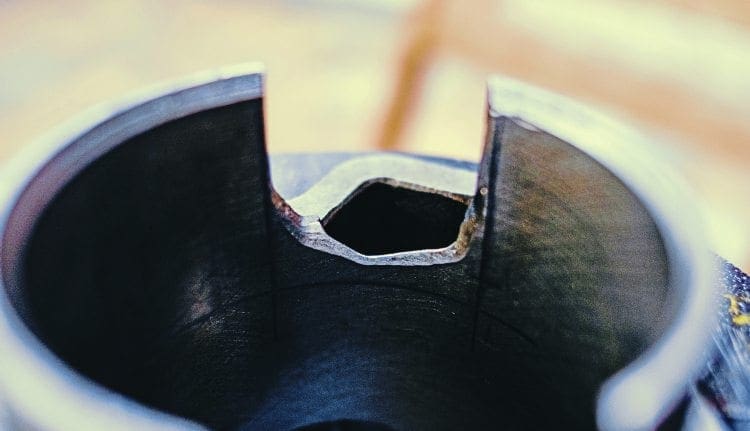
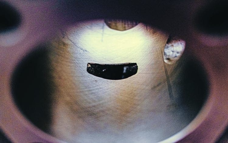
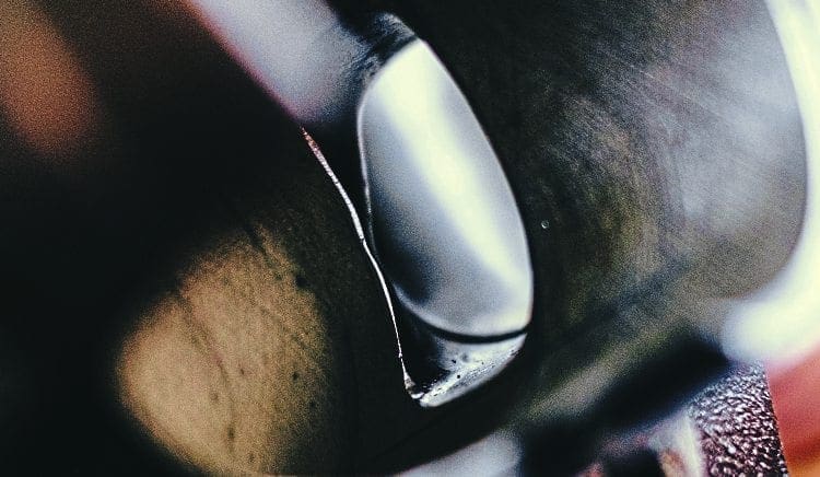
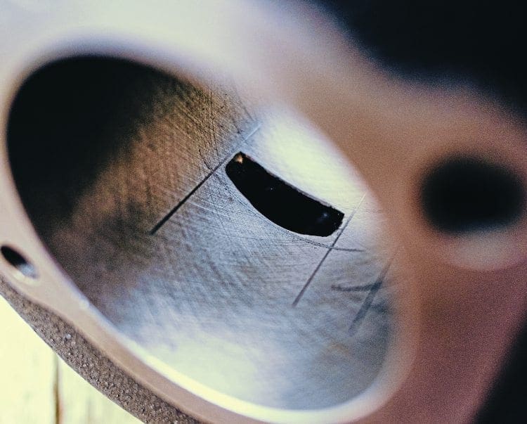
Chamfers and marking
Even if deciding to leave a SIL cylinder standard, it’s worth removing the cylinder anyway as I found the port edges to be razor sharp with no chamfers added, which will cause rapid ring-wear. The original three-ring piston was used for these tests but wasn’t planned to be used longer term (as noted in our part 2 ‘upgrades’ instalment).
The illustration pictures show horizontal and vertical working lines for initial port cutting but no corner radius or chamfers, the exhaust port needs to retain a similar shape to the original curved closing edge in order to ease the ring gradually back into the bore after passing this largest of ports.
Figures
So with the porting completed the port durations now looked like this
Exhaust port 188°
Transfers 126°
Inlet 149°
This arrangement gives a blowdown figure of 31° which is just a slight smidgen higher than preferred, but as a later development was set to utilise a 60mm stroke crank this was not a concern right now. The imminent 60mm crank would later increase transfer duration to
128-130 transfers as a result of stroking and revised packer/gasket combination.
Had I been tuning to a final 58/107mm and not just ‘step by step’ tuning, then the transfer setup I would go for would be 128 degrees, which would broaden the power spread. Again, if wishing to replicate the port specs, it would be based around the exhaust system selected.
The cylinder head would remain as before with its 1.05 squish clearance and therefore 9.03:1 uncorrected compression ratio, but with the exhaust duration now at 188° that equates to 5.31:1 corrected compression ratio figure. This corrected figure, which takes into account where the exhaust port closes, was nearly as low as the standard engine when we started with the big gasket, so upon testing I expect to see a loss in bottom-end lower rpm grunt which could be recovered later from an increase in this area.
The rest
The standard inlet manifold was flowed and matched to the cylinder and a second inlet for a 30mm Dellorto carb was also prepared for a later test, although other before/after tests in this area have shown little gains for me, unless a serious mismatch step exists in the direction of flow. Doing it in the example was a simple matter of ‘ticking the box off’ as it were.
So how were we going to handle the extra power with clutch slip occurring on the standard clutch components at around 15bhp? Well as it’s all about Bang for Buck, I decided to see how the standard clutch coped with just the lowest cost change possible. I purchased a set of five heavy duty clutch springs along with fresh oil at a quantity of 500ml. I’ve found mineral gearbox oil to work better than synthetic oils to reduce slip potential further.
Results
With the engine reassembled and leak-down tested, we got it refitted into the chassis and it was time to test the results. For the first test we wanted to see a true reflection against the last run, so the dyno graph of the motor on the mid-weight flywheel was selected for comparison as it was still fitted, and back on with the TSR pipe and 22mm carb. We were also quite lucky in the fact that the dyno tests done, despite being days apart, were very comparable on correction factor.
The results are very interesting, between 3500rpm and 5000rpm we are down between 1 to 2bhp when compared to the last test. The lower corrected-compression ratio, as a result of raising the exhaust port, I’m sure is the cause on this early test. But from 5000rpm to 7500rpm it’s up plenty with as much as 7bhp more at 7200rpm, peaking at 18.2bhp!
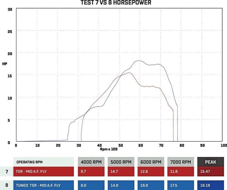
It’s worth noting that we are getting onto the pipes ‘power kick’ at around 4200rpm which is very good and making useful power to 7200rpm, so hardly a high rpm screamer! By comparison, the power of the old set-up fell off a cliff at 5500rpm and so would require very tall gearing to convert to higher road speeds, which in turn would then not accelerate as well.
What can now be done instead, is to look at the additional over-rev which is a useful amount of power from 5500rpm to 7500rpm and realise that the 2000rpm extra equates to around 20mph to play with on the gearing. A drop of one tooth on the front would only lose around 4mph of that 20mph and accelerate better to regain the drive lost at the bottom end. This is always worth considering if you’re doing pipe/kit swaps or tuning mods which increase or decrease the working rpm range.
Next test was to fit up the final choice of exhaust for the end user, an NK rally system (the green curve) and compare the two systems which worked quite similarly. The TSR (blue curve) having slightly better drive low down, and the NK slightly more over-rev, though the port specs were set at a duration I’ve found to work best on the NK. The TSR pipe, when fitted to a piston port/oval port cylinder, although it performs well requires a tuned length change for best results.
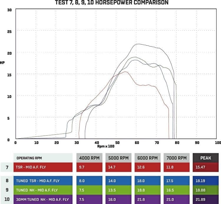
For this month’s last test the inlet manifold and carb were swapped for the 30mm Dellorto, having set a lot of these up on piston port motors the jetting was pre-fitted to a baseline setting, although each motor proves different to a degree but it still gets us close from the start. The test went well on the 30mm with clean jetting running at a similar air/fuel ratio to the previous 22mm standard carb so a fair test as there’s no point comparing a rich running carb to a lean running carb.
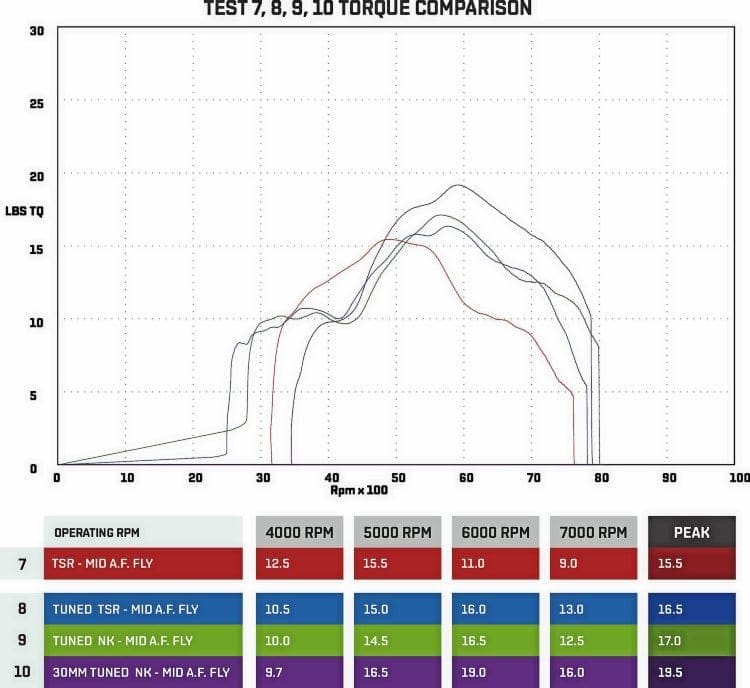
This time the big carb has come good (compared to lacklustre results in previous ‘standard engine’ tests) the purple 30mm graph vs the green 22mm graph shows nearly 3bhp more during peak power 6000rpm at 21.89hhp and around 4bhp (near 5bhp) up in other areas,
So we reached 21.9bhp and 19.5tq at only 200cc and 6000rpm on an old SIL 200 cylinder, not bad. The bigger surprise though… a standard clutch with just the heavy duty springs is holding up. It’s a lot heavier at the lever but the springs are new and so will bed in over time, a swap to a quality cable or a longer lever gets it back to being user friendly for those who would find it too stiff.
That’s all for this month, stay tuned.
Words & Photographs: Darrell Taylor
This article was taken from the August 2016 edition of Scootering, back issues available here: www.classicmagazines.co.uk/issue/SCO/year/2016

Enjoy more Scootering reading in the monthly magazine. Click here to subscribe.
Scooter Trader