With the first stage rebuild complete now the time has come to fit all of the bodywork and the final fixings.
This is where patience is a real virtue as great care must be taken to avoid scratching the paintwork. At any point, if something is not fitting right or the job in hand is getting awkward, walk away. By taking a breather you can come back with a clear mind ready to tackle the problem without getting frustrated.
Horncasting, mudguard and legshield fixings
The fitting of these two components virtually finishes the front end off. There are several methods of how to go about doing this, but in my experience it is better to do it piece by piece. There is a method whereby both the horn casting and mudguard are bolted together and fitted as one. However, this can lead to the problem of the rubbers sliding out of place or scratching off the paintwork as both parts bolted together can be heavy and cumbersome to hold.
Enjoy more Scootering reading in the monthly magazine.
Click here to subscribe & save.
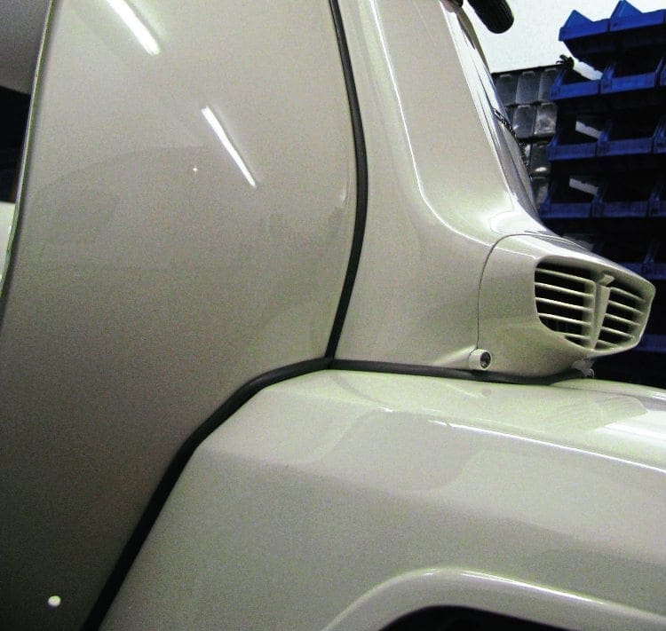
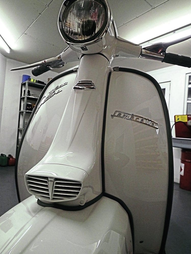
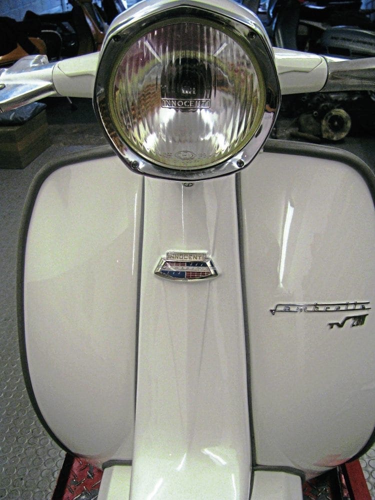
Before offering the horncasting to the leg shields, fit the front grille first. When it’s ready, insert both rubber trims on to the edge of the horncasting. These should sit perfectly in place but if they are a bit loose don’t worry at this stage and certainly don’t try to glue them in. If you do glue them in then chances are they will pull the paintwork off if you have to re-align them slightly, also residue will more than likely be on show.
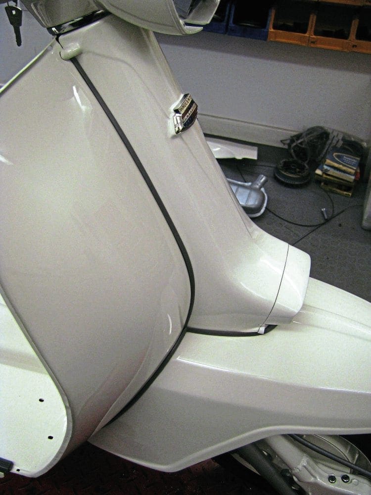
With the badge clip inserted, secure the horncasting to the frame by fitting the two 6mm Allen bolts. Slowly turn each bolt in, making sure that both rubber trims are in position and tighten until they touch the edge of the leg shields so they can’t pop out. Don’t fully tighten the bolts as this will allow movement to align the four screw holes on the inside of the leg shields. Now fit all four screws and slowly wind them in so they are nearly home. At this point, if everything is in line fully tighten the two Allen bolts. By doing this the horncasting should now be in the correct position and will take the strain off the four remaining threads as you tighten the screws up. Now you can proceed with fitting the front mudguard.
Firstly place the rubber gasket underneath the horncasting, which should sit in place without falling out of position. Fix the mudguard to the horncasting by way of the two 5mm bolts on the underneath. Again, don’t fully tighten to allow for adjustment. Now fit the four screws through the back of the leg shields, then the rubber gasket and finally through the mudguard. Remember, the two middle holes on the leg shields don’t have the screws fitted until the floor channels are in place. By tightening up these fours screws most of the way this will leave the mudguard near enough in its correct position. Now carefully position all three rubber gaskets into their exact position and tighten all the screws and bolts up. Now the leg shield trim and floor runners can be fitted. Before doing so, heat them up first so they are as flexible as possible when putting into the channels or on the outer lip of the leg shields.
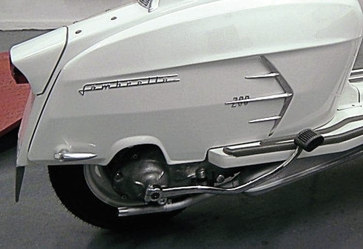
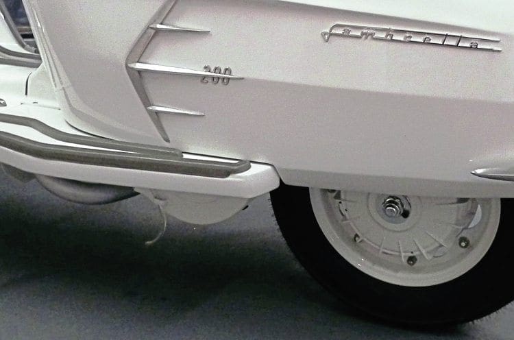
The final fitting on the leg shields and one that can be the most difficult is fitting the badges. Before placing the badge into position, make sure all the pin holes are clear. Don’t do this by pushing the badge pins through as most probably they will cause the paint to chip off as you do so. Take a small drill held in a set of pliers and turn it through the hole to clean all the paint out. Now flex the badge so it is exactly the same contour as that of the area it is been fitted to on the leg shields. Push the badge through the pin holes so it is in the exact position. The next process of opening up the badge pins requires two people if you are to do it without any mishaps: one person to hit the pin and one to hold the badge in position at the same time. To hold the badge requires a block of wood pressed up against its surface making it solid each time it is hit. Get an old piece of inner tube wrapped around the wood which will stop marking of the badge surface and prevent scratching the paint just in case the piece of wood slips.
From the other side, start off by hitting the centre of the pin hole with a pointed dot punch. Once the pin has splayed open it can then be hit with the ball end of the hammer to secure the badge fully. This process can then be repeated for all the leg shield badges.

Footboards and bridge piece
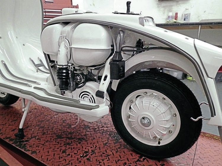
Fitting of the footboards is simple in the fact there are only three fixing holes but if not correctly lined up can look horrendous with a gap between the leading edge facing the leg shields. Start by placing the footboard in position to see if all three fixing holes line up with those on the frame. Though this was done on the dry build, sometimes they can be slightly out afterwards. If everything looks okay, place a vibration rubber under each hole and fit the outer floor runner. Now you will be able to see if both edges line up exactly.

If they don’t then it’s usually down to repositioning the hole on the rear strut. If the hole in the footboard and the rear strut are slightly out it is possible to make the one on the footboard slightly bigger so that they do. Remember the runner covers a slightly bigger area than the hole so this gives some leeway to the size you make it. Check everything lines up perfectly and fully tighten down the outer runner. This method can be repeated on both footboards.
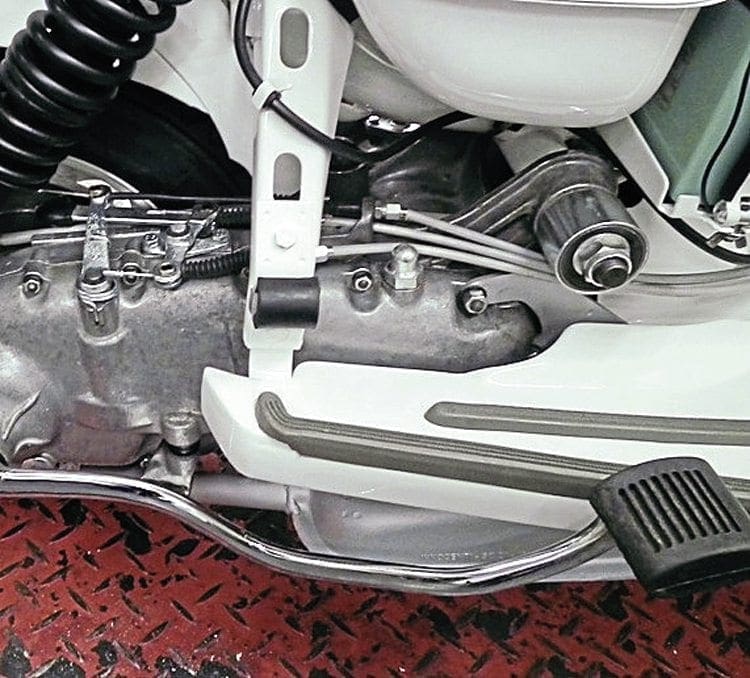
Before fitting the bridge piece make sure there are no obstructions from the carburettor cable and the cable shroud for the gear and clutch cables on the opposite side. If they are too close to the edge this can cause the bridge piece trim to bulge out. Place both trims on the bridge piece and offer it up to the frame. Make sure underneath both holes where the screws go there is a square vibration rubber inserted. If it is left out then this can cause the bridge piece to sink lower and bend the lip where it sits on the edge of the leg shields. With everything in position tighten up both screws but not fully to allow any repositioning of the two trims. Once you are happy everything is correct, fully tighten down. This should now leave you with both footboards and the bridge piece correctly fitted.
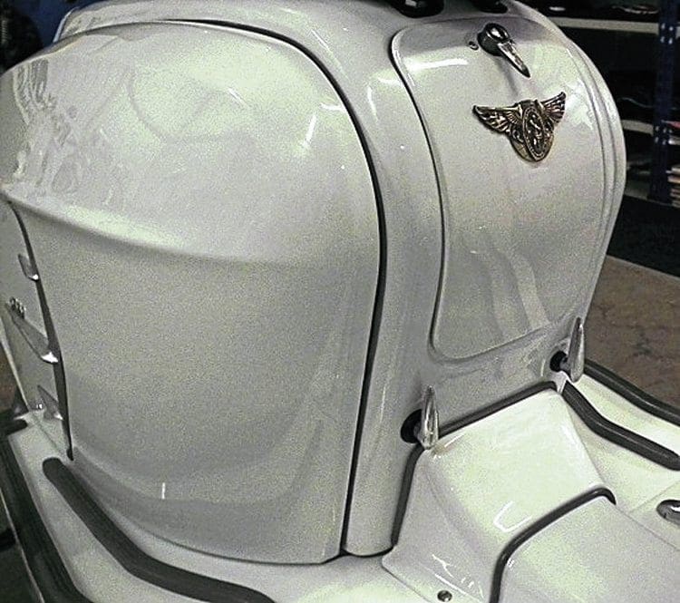
Seat and toolbox door
When fitting these two components start with the seat followed by the toolbox door. By doing it this way there is less chance of you catching the door which could flex out of position as it may cause an obstruction. Firstly bolt the seat post in position but don’t fully tighten. Now do the same with the seat but this time fully tighten all four bolts. Next, close the seat on to the post as it will move it exactly where it needs to be to lock correctly. If possible, tighten the 13mm nuts underneath so the post remains in position. Lift the seat so you can then fully secure them. Now you can check that the seat fully locks each time it is closed; this is required to pass an MoT.
Before fitting the toolbox door, its lock needs to be secured. It can be done with a rivet gun but if you want it to be correct you should use domed rivets and this will require the proper tools. And it will help if someone can hold the door while doing this process. Though this is only a small detail it is worth doing to give a proper finish. Once the rubber buffers are inserted into the door hinge place the pin through the hinge and close the door. If there is a bit of a gap at the top take the door back out and slightly bend the lock hinge inwards towards the door. Refit and check you have a tight fit at the top. If it is acceptable, open up the end of the pin so the door remains in place.
Headset top and side panels
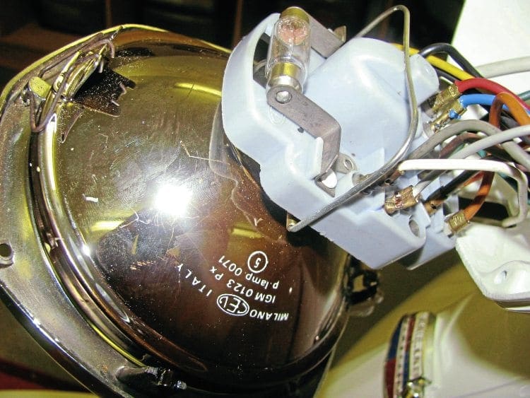
There are only two more parts of the bodywork to be fitted. The headset top and the side panels. Leave the side panels till last when you have checked the machine is fully up and running. This means the next process is to fit the headset top. Make sure that everything is working correctly in the headset including the cables, electrics and switches before starting. Also, lubricate and grease the cables where they go onto each pulley.
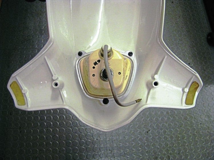
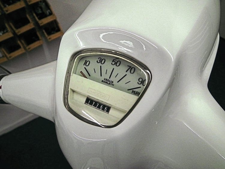
Before the headset can be put into position the speedometer will need to be fitted beforehand. Take care when pushing the speedometer into the recess as if the paint is too thick on the lip, chances are some paint will chip off. If the paint is too thick, very carefully sand the inner edge of the lip down to prevent this from happening. On the outer edge of the speedometer rubber, very lightly smear some grease as this will help ease it into the recess. Once fully pressed home fix in position with the retaining plate. Connect the speedometer cable but before doing so make sure it is working correctly by spinning the front wheel to make sure that the cable turns. Insert the speedometer bulb and then gently push the headset top down and into its correct position.
Insert both headset screws and tighten them up, alternating between each one to prevent the headset from lifting to one side. Make sure to watch the edges where the headlamp rim sits carefully and guide them exactly into position.
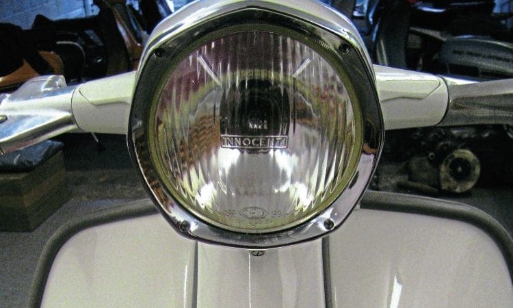
Now comes the critical part of fitting the headlamp rim. Before doing so it is advisable to clean out all four threads as there may be paint and dirt on the thread itself. Do this by running a 3mm tap gently down each one. It is also advisable to lubricate the thread so the screw has very little resistance when being inserted. Once happy clip the headlamp to the rim and offer it up to the headset. Position all four screws in their respective threads and alternate between each one until the rim starts to go into its recess.
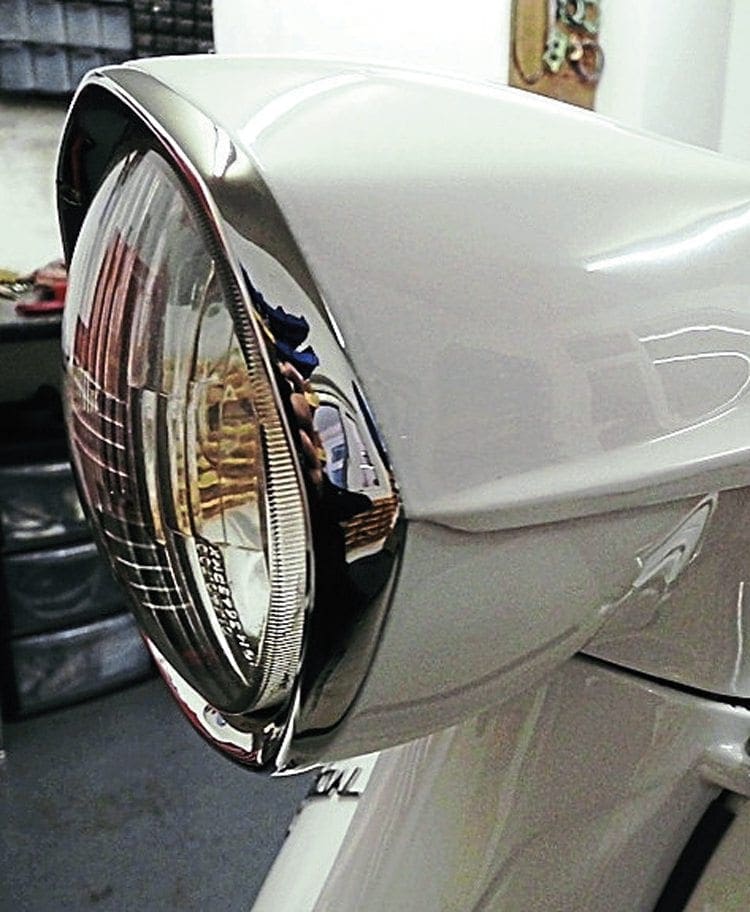
Now carefully start to fully tighten each one, again alternately and they should happy sit the rim in its exact position. If the rim doesn’t sit home perfect in one corner slightly loosen off the screw in the opposite corner allowing it to locate 100%. This may take a bit of doing before fully tightening each one up for an exact fit all round. Once this is done make sure all the electrics are working correctly as on the odd occasion a wire can pop out during this process.
Remember though, the headlamp rim has now shaped itself perfectly to the contour of the headset, so when it’s removed anytime in the future, it should always go perfectly back into position. This now leaves just the side panels which are not bolted in any way but need the badges and handles mounting. Fitting of the badges will definitely require two people as the panel is not fixed down. Repeat the process of cleaning all the pin holes with a drill before commencing. If you have a vice place the wood block you used before in the jaws and tighten up at much as possible. Place the badge in position and then rest the badge on the wood block remembering to put the rubber in between to prevent damage to the badge. Repeat the process of splaying the pin and then hitting the end over to secure. This will take great patience but one person holding the panel in place while the other hits each pin is the best method.
When fitting the panel handles, make sure you have them the correct way round before securing, especially if it’s the fixed handle type that uses a split pin. It’s easy enough to check but make sure you do so as to avoid any unnecessary swapping around. Try the side panel on the frame to see if the fit is still good. Make sure the side panel beading on the frame is sitting fully home and is the correct length, not protruding at either end. Also, remember to have the side panel buffer in position.
Now place the panel in the recess and sit it fully home followed by locking the handle in position. Check to see that it sits fully in the recess all the way round and there is enough of a gap between the bottom of the panel and the footboard. It is possible to lower or raise the footboard slightly by either adding another vibration rubber or, on the kickstart side, adjusting the removable footboard bracket. If the dry build was done correctly though none of these problems should arise.
Apart from the finishing touches, everything is almost done. In the last part of this series, we will look at doing the first shakedown run out on the road.
Words & Photographs: Stu Owen

Enjoy more Scootering reading in the monthly magazine. Click here to subscribe.
Scooter Trader